

By: Jeff Koellmer
Some time ago, Märklin® introduced a series of less-expensive locomotives equipped with digital decoders and special motors. The locomotives are numbered in the 368xx series and are considered part of their Hobby line. Several chapter members have purchased the models and were very impressed with the quality and running characteristics. These locomotives, however, were not equipped with sound. Many modelers believe that the sound component adds a new dimension to model railroading.
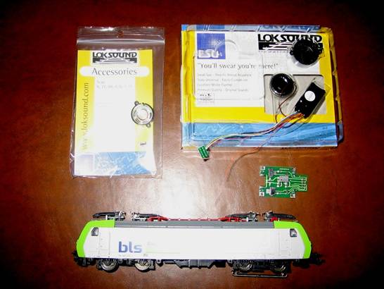
Recently, fellow chapter member Mark Mervine and I added a Loksound v3.5 decoder to one of the new Märklin® Hobby locomotives. This article describes how we accomplished the installation. The technique and identification of parts required are credited to a Mr. Lutz Hemmerich, whose information is posted on a website elsewhere. Our thanks go to Mr. Hemmerich for introducing us to this exciting solution. In addition to the 36852 Class 485 electric locomotive, the parts needed for our installation were as follows:
a) Märklin/Trix® Part Number 611654, Circuit Board (equipped with a NMRA standard 8-pin plug).
b) Loksound v3.5 Digital Decoder, ESU® part number 524xx.
c) 0.79” Loksound speaker, ESU® part number 50441.
These parts can be obtained from your Märklin® and ESU dealers.
(Click on Images to Enlarge)
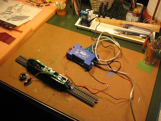
An ESU® Loksound programmer attached to a Personal Computer (PC) was also used to adjust the decoder’s settings once the installation was completed, but this can also be accomplished with other devices (your Märklin® 6021 Control Unit or IB). Other tools required for the installation were a soldering iron, Dremel rotary tool with grinder attachment, wire cutter, needle nose plier and small screwdriver. Some clear silicone sealer and a small wire tie were useful as well in completing the installation. We found that it helped to have two people working to aide in the de-soldering/soldering process (extra set of hands) as explained further below.
Step 1 – Remove the Locomotive Body
The first step in the process was to remove the locomotive’s body. There is typically one retaining screw that is accessible when the locomotive is inverted and placed on a work surface. Access to the motor and electronics was available when the locomotive chassis was set upright.
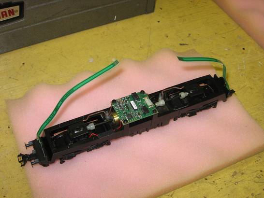
Step 2 – Disconnect the Headlamps
In preparation for replacing the existing circuit board, we disconnected the headlamps that were located at both ends of the unit. We carefully slid the ribbon cables from their respective sockets on the circuit card and tucked them into the chassis at both ends to permit easier access to the circuit board.
Step 3 – Replace the existing Circuit Board
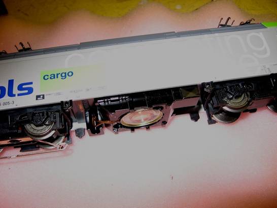
The next step in the process was the most difficult, but was made easier with two sets of hands. First, we disconnected the power pick-up cables from the circuit board. There was one red wire and two brown wires soldered to each of three corners of the circuit board. We unsoldered these three wires and moved them out of the way for the time being.
We removed the circuit board from the chassis by first taking out the four retaining screws, and then by lifting the board/motor assembly out of the chassis. The cardan shafts leading to the driving wheels became unseated in this process but were easily reset later on. We found a small piece of double-faced tape between the old circuit board and the motor. With the circuit board/motor assembly now apart from the chassis, we gently pried the circuit board upwards to loosen the tape. The motor was attached to the circuit board by two “globs” of solder. While I heated up both globs with my soldering iron, Mark applied gentle pressure on the motor to slide it away from the old circuit board (a little tricky..),. Once free, the old board was set aside.
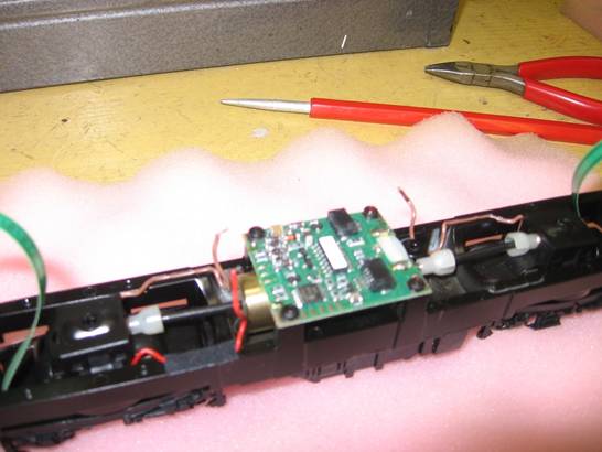
The new circuit board (part a. listed above) was then installed by reversing the process of reheating the solder “glob” and sliding the circuit board into the position vacated by the old board. The drive shafts were reset and the new circuit board/motor assembly re-installed using the four retaining screws. The three power pick-up cables were re-soldered to the contacts in the respective corners of the new circuit board. The headlamp ribbon cables were reconnected.
The end result was that a new circuit board containing an eight-pin receptacle now replaced the older circuit board. The new Loksound decoder (Part b. above) was plugged into the receptacle on the circuit board. Before continuing, we decided to perform a bench test. We placed the chassis with the new circuit board and Loksound decoder on a special programming track. We used the ESU Programmer connected to a PC, to test out our progress and make sure all was working as anticipated. The new decoder worked flawlessly (although we had to re-seat the 8 pin plug once). Each available function was checked in turn and the sounds were impressive!
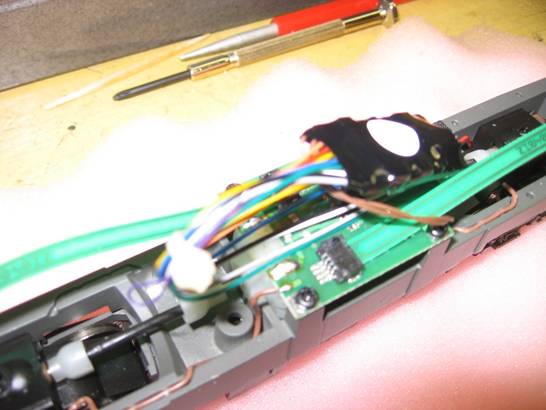
Following the bench test, the chassis was returned to the work table. To complete the installation, the speaker needed to be mounted onto the chassis. Because the speaker included with the decoder was too large for the locomotive’s sound chamber, it needed to be replaced with the new 0.79” speaker (Part c. above). We unsoldered the two wires from the stock speaker and fed them down through the hole toward the sound chamber. We took care not to confuse this hole with the one required to secure the locomotive body to the chassis. We then soldered them to the new speaker at the solder points provided. We then inverted the chassis on the work surface.
Step 4 – Install the New Speaker on the Chassis
We found it necessary to mill the side of the sound chamber slightly so that the speaker wires would exit the chamber while the speaker sat flush on its mounting rim. A Dremel tool equipped with a small milling bit was used to “slice” a groove into the sound chamber’s casting on the side leading to the access hole. Care had to be taken to not over-mill and to remove all of the metallic shavings before continuing.
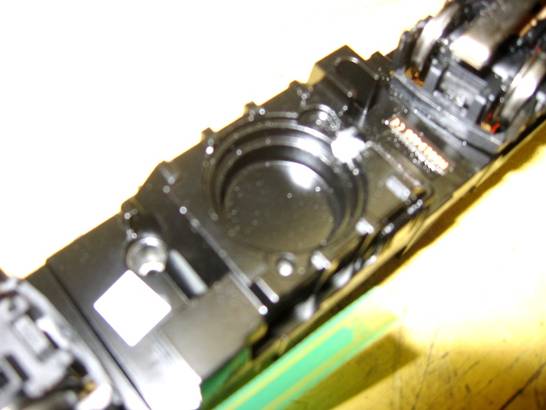
When enough material was removed, we applied a small bead of silicone around the edge of the chamber and set in the speaker. We then tucked the excess speaker wire up into the hole in the chassis so it would not come into contact with the track.
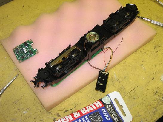
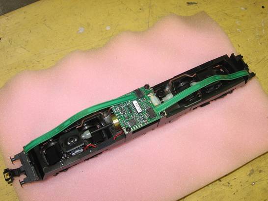
Our installation was virtually complete. We set the chassis upright again, secured the new decoder in place using a spot of double faced tape and bound up excess wiring with a small wire tie. Our installation looked like the following:
Step 5 – Replace Locomotive Body
All that was left to do was to re-install the body on the chassis, place the locomotive on our layout and dispatch our creation while enjoying the sound of its engine, horn, conductor’s whistle and even a station announcer; all controlled by function keys on our controller. Overall, we found the process to be straight-forward, quick and well worth the effort and small added expense.
©2008 ETE Eastern New England Chapter. All rights reserved.