
By: Jeff Koellmer
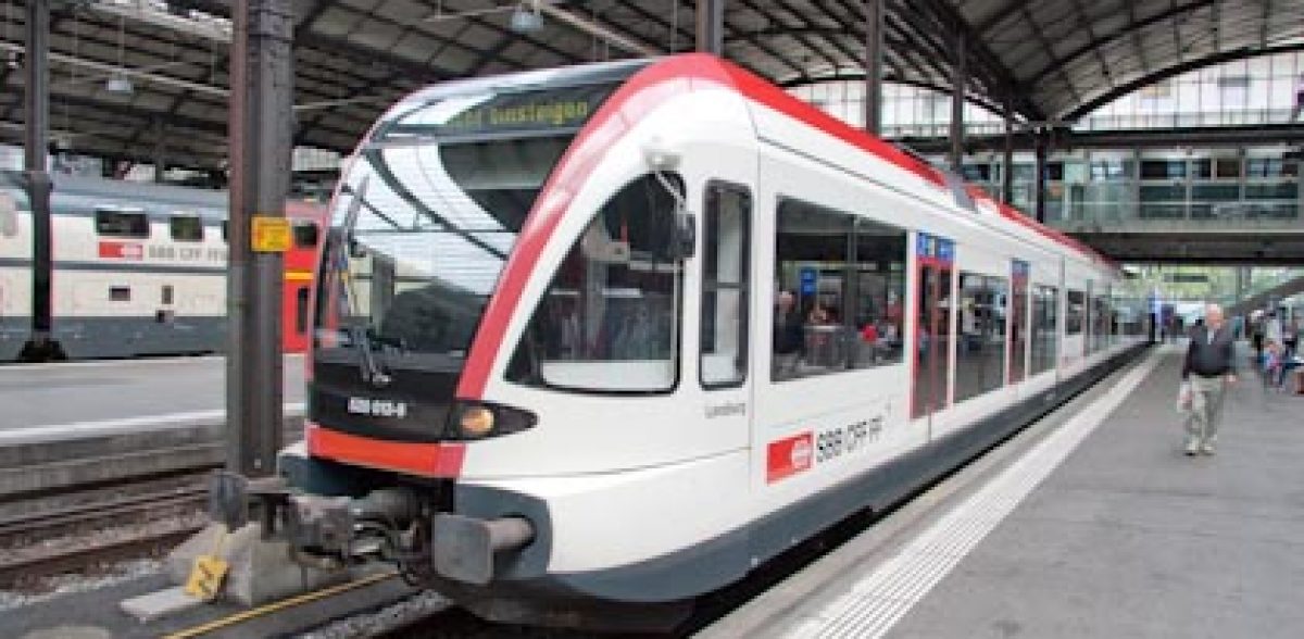
While planning and building my HO scale Marklin digital model railroad layout, I decided it would be interesting to have a bus traveling through my scenery. I could have just placed a stationary bus at some point, but I did some research and decided I wanted an automated vehicle. My layout contains many “motion-oriented” components in addition to the trains themselves. A colleague impressed me early on that “the more motion you can incorporate into your layout – the better!” I seemed to have picked up on that mantra and have included many moving components in my relatively small layout space (10’ x 7’, L-shaped). Since I model modern-day Switzerland (also referred to as Era V), I began my search for a Swiss Postal Bus; typical of what you might see traveling the streets in Switzerland. Gebr Faller GmbH of Germany makes a line of automated vehicles that are battery powered and follow a path containing an embedded guide wire. The only bus I was able to find was in Start Set Number 1634. This set contained an Intercity bus that might be found traversing the cities and countryside of Europe, including Switzerland. I would have to make this do. The kit is pictured below:
(Click Images to Enlarge)
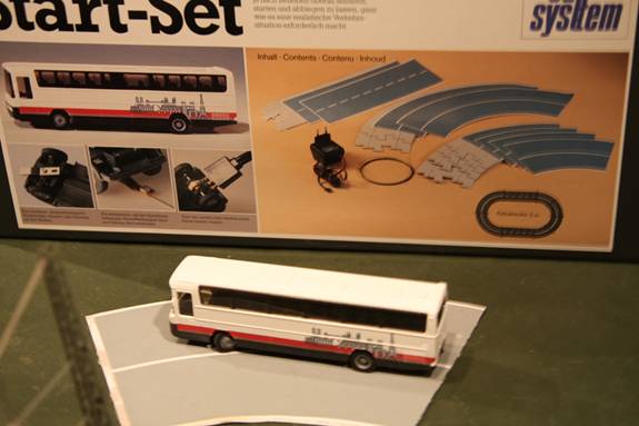
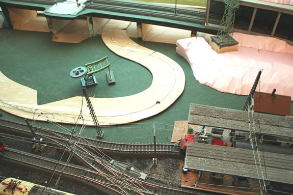
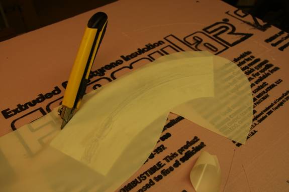
In addition to the bus, the kit contained a length of guide wire and an oval of interlocking, short roadway sections for the bus to follow. Roadway sections in both straight and curved configurations were included. Each cardboard section contained a V-groove in both directions for two-way travel, and a set of vinyl surface sheets to cover the wires once taped in place. You can purchase additional sections of roadway to make other shapes and paths, but my limited layout could not accommodate the wide radius. This roadway was obviously for a major, two-lane highway, further suggesting that I find another method of implementing the system. My layout was to include lesser “country roads” anyway. I pretty much knew the pathway that I wanted the bus to traverse, but was a little concerned that it would not be able to negotiate the tight corners that I needed. So, my first step was to map out the route through my layout and tape the guide wire directly to the table top. I then covered the wire with plain copy paper for a test run. I was pleasantly surprised to find that the bus could make the tight turns and complete the loop successfully. Since I planned to run only one bus in the same direction, I decided on a roadway of about 30 scale feet in width. I also decided to make my own sections of roadway using 1/8” panel board. This is the typical panel board you might use for wainscoting that I bought at my local Home Depot. I tried to make the sections as continuous as possible, reducing the number of joints that could affect the running bus. Using my saber saw, and after making a few paper templates, I cut the panel board to the shape of my intended route, then dry-fit them to my layout. The path my bus was to follow around and under my elevated track is shown below.
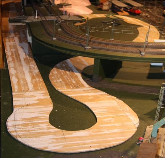
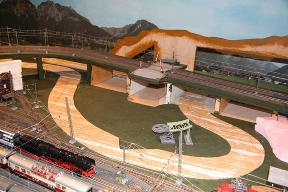
Notice the “notch” in the roadway panel immediately behind the pulley mechanism? The pulley is part of an alpine gondola that I had already fixed to my layout. Remember my earlier comment about lots of moving things? I love this gondola and had spent many hours getting it properly aligned and operational, with a mid-way tower and peak station on a mountainside. At that time, I envisioned a single lane roadway passing behind the base station, but not a thirty foot roadway. I didn’t want to move the pulley and base station, so I thought that a little obstruction in the roadway might be an interesting twist. I would make this work! You’ll see the result later.
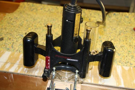
My next task was to bury the guide wire in the panels. I fit my Dremel Moto tool with a plunge router attachment, V-groove bit and a guide that would ensure that my grooves were placed where I wanted them into the roadway sections. The following picture shows my Dremel tool and a section of roadway being routed. This process worked well, although I was forced to do some free-handing in places where I wanted the bus to travel towards the middle of the roadway to clear an underpass abutment, for instance.
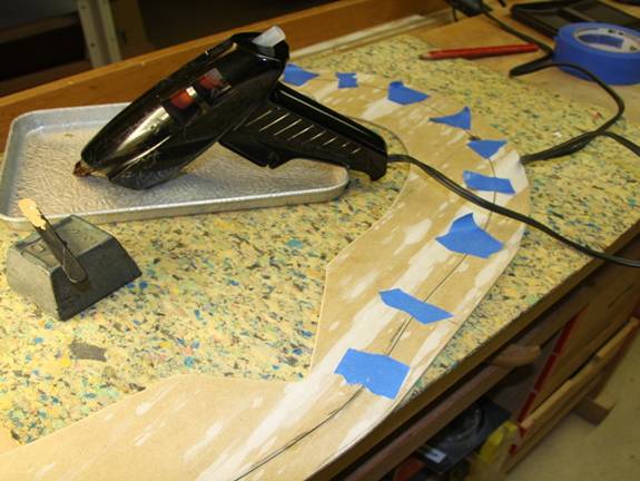
Once I had each section of roadway routed (there were five in all), I cut the guide wire to length for each section, overlapping about ½” into the adjoining section for continuity. Achieving the proper depth for the V-groove was tricky in spots. Care had to be taken to ensure that the wire was far enough buried into the wood surface so as not to be noticed, yet not so far as to render the magnetic property inoperable. When routing was complete, I temporarily taped the wire in place and used my hot-glue gun to seal the wire into the groove as pictured below:
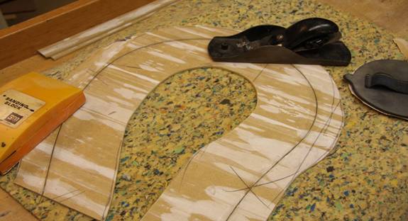
Once the glue set, I smoothed any of the high spots with a small hand planer, a hand-held sanding block and even a belt sander. This worked fairly well, although I had to be careful not to scrape too far below the surface for fear of slicing through the fine wire. The belt sander worked only marginally as the hot glue quickly clogged the pores of the sandpaper. Only a quick swipe was allowed. A section of roadway’s end loop with its embedded wire appears below:
Once all sections contained their guide wires, I needed to cover them with material similar to what came with the start set. Before doing that, however, and since I wanted the bus to stop occasionally to allow passenger access, I purchased a magnetic stopping coil from my Faller dealer. This is an accessory that Faller offers (Item No. 161675), to be mounted into the layout which, when activated with a small 12 volt DC charge, interrupts the bus motor and causes it to stop in place. I determined where I wanted this device and bore two holes: one for the device and a corresponding hole into the roadway section. I connected the coil to a small doorbell button placed below the layout for activation. My grandchildren love to “stop the bus” with this button. Below, you can see the imbedded coil adjacent to the train station:
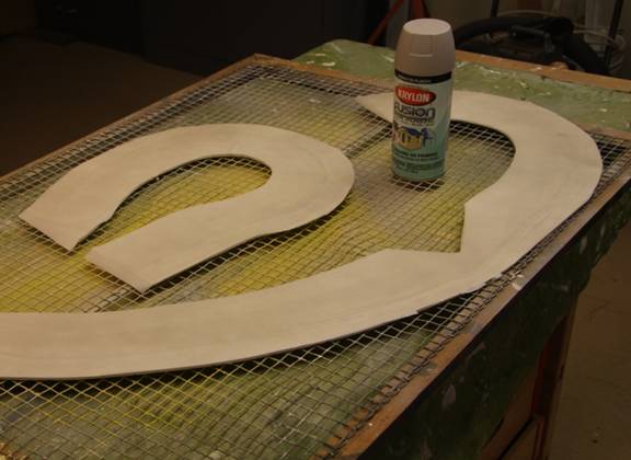
Now I was ready for covering each section. I didn’t think painting would be a good idea because of the magnetic wire, so I resorted to material similar to what came with the set. I found a roll of plain-colored, self adhesive contact paper at my local hardware store. This stuff is normally used to cover shelving in linen closets or kitchen cabinets. I applied contact paper over each roadway section and trimmed each piece to fit with a razor knife. Again, I allowed a half inch of overhang at each end for placement onto the adjoining section.. I soon noticed that the self adhesive was not quite durable enough to stay in place as I handled each section. So I carefully removed each contact paper piece and sprayed the wood with an artist’s adhesive made by 3M Corporation called Spray Mount Artist’s Adhesive #6065, purchased at my local craft supply store. Then I re-positioned each one. As the last step in this process, I decided to spray paint the sections with a concrete color for improved appearance. I found a paint made especially for plastic called Krylon® Fusion at my local paint store. The two images below show the result of this process:
I was now ready to put each section in place permanently on my layout. A little wood glue on the back side of each section did the trick! I made sure each section was aligned and that the imbedded wires were contacting one another, with the contact paper overlapping in the direction of travel. With all sections in place, a final test run with the bus resulted in success! I still needed to place some lines in the roadway for center lines, crosswalks, traffic stops and general borders. For this I turned to 1/8” self adhesive pin stripes that I found at my local auto parts retailer. I carefully cut, peeled and placed the white stripes on the roadway.
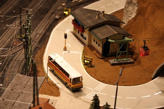
I was very impressed with the realism and motion of the bus in operation, but still disappointed that it wasn’t a Swiss Postal Bus. I decided to paint the bus and add a driver and some passengers. I found a picture of a prototype bus on the internet, matched the colors using my airbrush, and converted the “city bus” to a “postal bus”. Again I turned to 1/8” pin stripes for the red line that bisects the sides of the bus. My scenery is not yet complete (no grass on the hillsides), but you can see the result of my efforts in the picture below. Oh, and about that “notch” for the gondola’s base station, I installed a few flashing caution lights on the side of the road and the corner of the building, added a traffic light and now have a genuine conversation piece! The bus passes nicely behind the base station and a traffic light will let two-way traffic share the limited roadway!
©2011 ETE Eastern New England Chapter. All rights reserved.