
By: Mark Mervine
Background: The first Märklin models of an ICE were of the ICE Experimental prototype. Märklin produced two versions of this set; the model number 3371 was an analog version and the number 3671 was the digital version. Both versions had two powered units and two center cars. A third center car (to match the length of the prototype) was made available from Märklin as model number 4171. These models are no longer produced, but they do come up often on the second-hand market. I was able to obtain a 3371 set a couple of years ago but, since it wasn’t digital, it sat on my display shelf. Through a recent discussion on the Märklin users-group network (http://www.marklin-users.net/), I became aware of third party products to allow for the digital conversion of the 3371 set. I chose a set of new circuit boards from Digital-Bahn (see http://www.digital-bahn.de/bau_fzg/ice.htm) that sell for approximately 25 Euros. The circuit boards are identical but, due to their clever design, only one is populated with elctronics and only one decoder is required to drive both motors. The boards also have standard eight-pin socket to enable plug-in of a decoder. I also chose a LokPilot digital decoder manufactured by ESU for the conversion. Fellow ETE member Jeff Koellmer and I undertook the conversion recently. Tools and materials required for the conversion were pretty much limited to the usual compliment of micro- screwdrivers, a small Soldering Iron, solder, some soder-wick® type product, a LokSound Programmer (or 6021, IB, etc. that can change the new decoder’s Configuration Variables, if necessary), and a length of test track. You’ll also need some fine-gauge wire as well.
Control Unit: Carefully remove the car bodies from both end-units of the set to expose the motors and electronics. The power car with the green circuit board is the one that will get the Digital-Bahn circuit board (with electronics) and decoder (see Figure 1, below). I refer to this unit as the Control Unit in the remainder of this article.
(Click on Images to Enlarge)
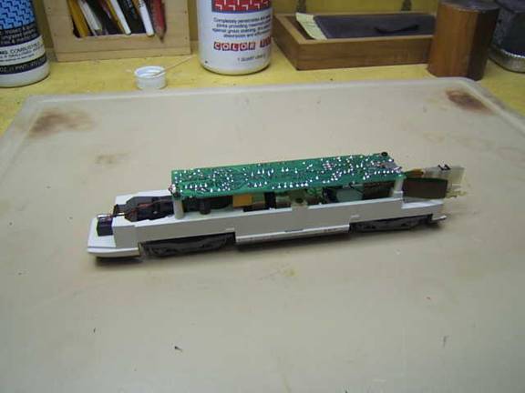
Figure 1- ICE locomotive’s Power Car with body removed
The next step in the process is to de-solder the three light wires, the two motor wires, and the pickup shoe wire from the Märklin circuit board. Remove the circuit board from the car base via the two corner screws. Note the location on the circuit board where the 8-pin ribbon cable (that connects the cars) protrudes. Again using a soldering iron, carefully wick away as much solder as possible from the pin points. When most of the solder has been removed, pry the ribbon connector free from the circuit board. Tip: We found it most helpful using two sets of hands when performing this step. Any solder remaining on the ribbon pins must be heated at the same time pressure is applied to extract the pins from the circuit board. When the ribbon connector is free, you are ready to replace the old circuit board with the new one (see figure 2, below).
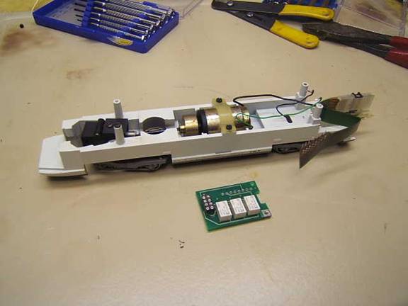
Figure 2- Control Unit, Ready to Install New Circuit Board
First, solder the ribbon connector to the respective pins in the new circuit board, then the two motor wires and the pickup shoe wire as shown on the Digital-Bahn website. The green motor wire is connected to solder point M1 and the black to solder point M2. Because the new board is shorter than the original one, longer wires will be needed to re-connect the lights. The white light wire is connected to solder point L1, the red light wire to L2, and the ground wire to SZ. Tip: Use as thin a wire as is possible to prevent any chaffing with the movement of the trucks. There is very little clearance between the truck and the new wires once the shell is re-attached. Before attaching the new circuit board to the car body (only one of the two original screws is required), plug the decoder into the socket on the underside of the circuit board using its standard 8-pin plug. Pin 1 of the socket is clearly marked on the circuit board and on the plug. Both must be properly aligned. Since one decoder will drive both units, be sure to select a decoder that can handle two motors. Cable ties and/or braided wires help to neaten up the job. Figure 3 below shows the completed installation.
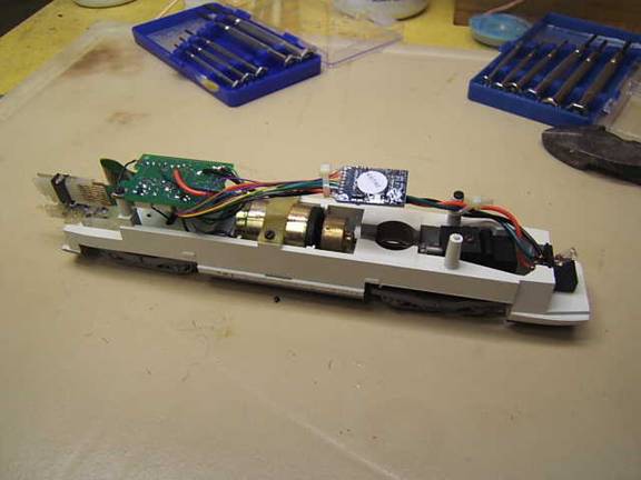
Figure 3 – Control Unit, after Installation
Before converting the non-control unit, I found it useful to test the Control Unit. Put the unit on the test track and make sure that it operates correctly and that the head lights work (the lights are controlled on/off by F0).
Non-Control Unit: Unlike the Control Unit, the non-control unit has a white Märklin circuit board (see Figure 4).
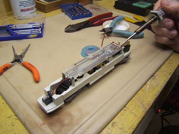
Figure 4- Non-Control Unit before Conversion
Use the same process as before to remove the wires and ribbon connector. Once these have been removed, solder the new board to the ribbon connector. Then connect the pickup shoe wire as before. The next step is to connect the motor wires. This time the green motor wire is to be connected to solder point M2 and the black to M1. The light wires are next. For this unit, the white light wire is connected to solder point L2, the red light wire to L1, and the ground wire to SZ.
Screw down the new circuit board (again using only one of the two original screws). Next, couple this unit to the Control Unit on your test track (see Figure 5). If everything is wired up correctly, the units will run synchronized together and the white/red lights will shift with the direction of travel. I found that my lights were working, but in the opposite direction of the motor. This was easily corrected by using my LokSound Programmer to change the reverse direction CV in the decoder’s setup file.
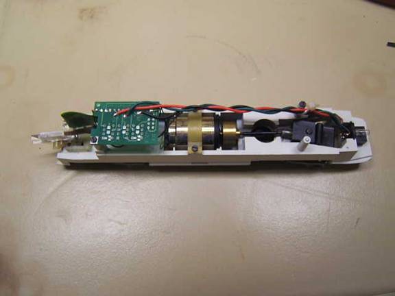
Figure 5- Non-Control Unit, after Installation
The final test is to connect one of the center cars between the two power units. With the car connected, make sure that the ICE operates as before. The lights in the cars can be controlled on/off using F1.
Features and Limitations:
The upgrade has the following features:
The 3371 set can now be operated digitally
The headlights can be controlled on/off with F0
The car interior lights on/off by F1
However, the upgrade has the following limitations:
The Digital-Bahn boards do not support pickup shoe switching. Instead, both pickup shoes are used to supply power in both directions.
The Digital-Bahn boards use relays, so it is not possible to turn down the intensity of the head lamps.
It is no longer possible to use the catenary for powering this set post conversion.
Conclusions: I am very satisfied with this upgrade. The Märlkin number 3371 set is a great set. If you like high speed trains, the ICE Experimental is a chance to run a prototype length ICE on a small layout. Tip: One thing that is not mentioned in the 3371 manual is that this set really needs radius R2 curves to operate smoothly. To run on radius R1 curves, the vestibule center connectors need to be removed. These come off easily. But when removed, it’s harder to couple the units.
©2008 ETE Eastern New England Chapter. All rights reserved.